
Choosing Adss Fibra Optica for a global project is not simply a matter of counting fibers or comparing prices. The cable must survive real places: humid coastal air, frozen mountain roads, intense sunlight, and long spans between utility poles. A design that performs well in Spain may fail in a tropical region if its sheath, fittings, and span calculations are not adapted.
Dr. Bob Chomycz, a recognized fiber-optic engineering author, offers a practical reminder: “The cable must be designed for the environment, not merely for the specification sheet.” That principle guides this outline. It encourages project teams to examine fiber type, tensile strength, creep resistance, jacket material, installation tension, and expected wind or ice loading. It also supports careful review of IEC, ITU-T, and local utility requirements. Compliance is not paperwork alone. It affects safety, maintenance, and long-term network reliability.
Details matter.
A reliable selection process should compare supplier experience, factory testing, traceability, warranty terms, and field support. OTDR results, attenuation records, drum protection, and connector compatibility deserve attention before shipment. Some buyers focus too heavily on the lowest quotation. That choice can create higher costs later through damaged cables, difficult repairs, or repeated installation work. Still, no checklist is perfect. Local data may be incomplete, and project assumptions can change after construction begins. Therefore, engineers should document uncertainties and revisit the design before approval. This guide explains how to evaluate Adss Fibra Optica with practical judgment, technical evidence, and a clear view of global operating conditions.
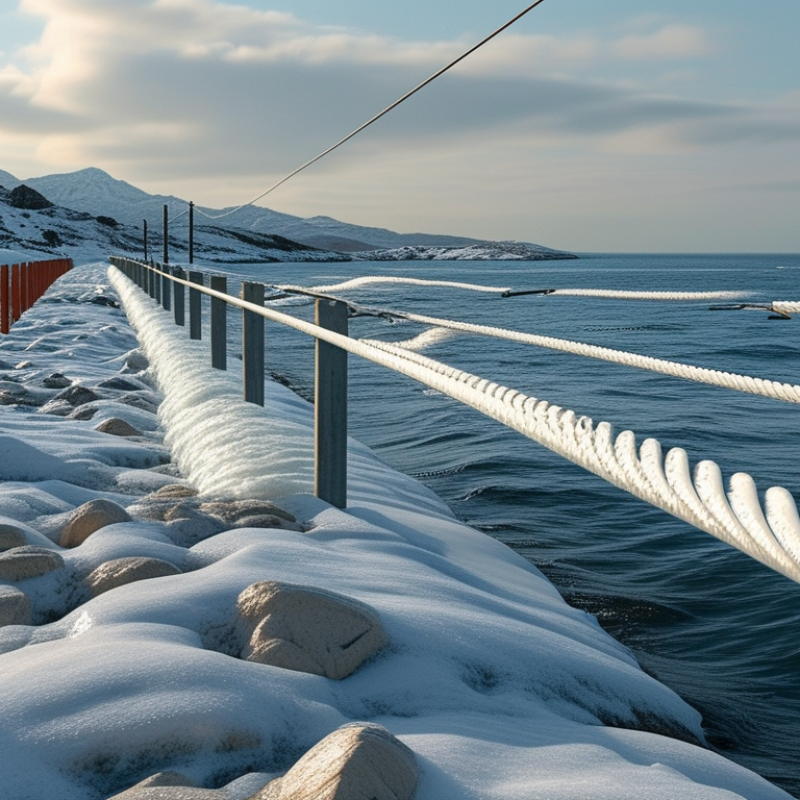
ADSS fiber optic cable is an all-dielectric, self-supporting cable designed for aerial installation. It contains no metal messenger wire. This reduces electrical interference near high-voltage lines and simplifies pole-mounted deployment. Engineers commonly use ADSS for rural broadband, utility communication networks, railway corridors, and long intercity links.
Project selection should begin with the route environment. Measure span length, wind pressure, ice loading, temperature range, and pole strength. A cable suitable for a dry region may perform poorly in coastal air or freezing conditions. Fiber count and transmission requirements also matter. Single-mode fiber usually supports long-distance communication and future network expansion. Check attenuation, tensile strength, jacket material, and expected service life before approval.
Installation details deserve equal attention. Correct sag control protects the cable during seasonal temperature changes. Improper tension can create stress at fittings. Small mistakes become expensive later. Experienced teams should verify tower clearance, grounding practices, local safety rules, and applicable international standards. Factory test reports and field acceptance tests improve traceability. Still, no design is perfect. Route data may be incomplete, and weather assumptions can be optimistic. A careful review should include realistic maintenance access, replacement planning, and regional construction skills. Conditions change. Good engineering leaves room for that.
Assessing network requirements across countries requires more than counting fibers. The ITU reported 5.4 billion internet users in 2023, representing about 67% of the world’s population. Demand is uneven. A dense Asian corridor may need high fiber counts and short spans, while a rural African route may prioritize long reach, rapid installation, and easy maintenance. Measure current traffic, forecast growth, and identify critical services before specifying the cable.
ADSS, or all-dielectric self-supporting cable, suits many aerial routes because it contains no metallic messenger. However, every region creates different stresses. Check span length, wind pressure, ice loading, ultraviolet exposure, temperature range, and pole strength. Coastal routes need stronger moisture protection. Mountain routes need careful sag calculations. Near energized lines, assess electric-field conditions and required clearances under local utility rules. IEC 60794 testing and relevant national standards can support a defensible specification.
Capacity should also reflect future traffic. Ericsson’s November 2024 Mobility Report measured global mobile data traffic at approximately 157 exabytes per month in the third quarter of 2024, excluding fixed wireless access. That figure makes low fiber counts look risky on fast-growing routes. Still, more fibers are not always better. Higher counts can increase cable diameter, weight, and installation tension. I would verify real loading data with local engineers, because regional assumptions often fail in the field. The most reliable design combines route surveys, climate records, utility requirements, and a realistic ten-year demand model.
How to Choose Adss Fibra Optica for Global Projects?
Selecting ADSS Cable Design, Fiber Count, and Span Performance
Choosing ADSS fiber optic cable for a global project starts with the route, not the catalog. Field teams should record pole spacing, terrain, wind, ice, temperature, and nearby power conditions. A coastal span may face salt and strong gusts, while a mountain route may demand greater clearance. These details shape the cable design, including jacket material, aramid strength members, and allowable installation tension. Small errors matter.
Fiber count should match today’s links and tomorrow’s upgrades. Count active fibers, protection paths, maintenance reserves, and likely expansion. A 24-fiber cable may suit a short access route, but a 48- or 72-fiber design can reduce future aerial work. Avoid filling every fiber on day one. It leaves little room for failure recovery. Fiber type should also fit the network, transmission distance, and equipment requirements. Confirm attenuation, bend performance, and testing data through traceable factory reports.
Span performance needs engineering, not a rough distance estimate. Review maximum span, sag, clearance, everyday tension, and short-term loading under wind or ice. A longer span can lower pole costs, yet it may increase sag and installation risk. Use route-specific calculations and verify them against applicable IEC standards and local utility rules. Include dead-end and suspension hardware in the design review. A neat spreadsheet can still be wrong. Recheck assumptions after a site visit, especially where poles change height or direction. Installation crews need clear tension tables, approved pulling limits, and practical handling instructions. That is where a promising design meets reality.
The chart compares representative ADSS cable planning values by fiber count. As fiber count increases, cable mass generally rises, while the indicative maximum span may decrease under the same structural design conditions. These values are engineering planning references rather than product ratings; final selection must consider wind speed, ice loading, sag, terrain, installation tension, temperature range, and required safety factors.
How to Choose Adss Fibra Optica for Global Projects?
Comparing Environmental, Safety, and Installation Conditions
ADSS fiber optic cable must match the route, not just the required bandwidth. Global projects expose cable to heat, frost, ultraviolet radiation, salt spray, and strong wind. Survey the worst season, not the average day. Record temperature ranges, ice loading, span lengths, and pole conditions before requesting a quotation. In coastal areas, moisture-resistant materials and sealed fittings deserve close attention. A cable that performs well in a dry test yard may age differently beside an ocean.
Safety conditions require equal care. ADSS has no metallic conductor, which reduces electrical risks near energized lines. However, it does not remove every hazard. Crews still need verified clearances, controlled lifting procedures, and suitable personal protective equipment. Check the cable’s rated tensile strength, maximum sag, and approved installation tension. These figures should come from traceable test reports, not sales language. Small errors in pole spacing can create excessive sag.
Installation hardware should suit the cable diameter and local support structure. Confirm dead-end grips, suspension clamps, grounding arrangements, and bend limits before delivery. Keep pulling tension within the documented limit. A practical route survey often reveals obstacles that drawings miss, such as narrow roads or unstable poles. I would also allow spare cable length at closures. It costs more initially, but rushed repairs cost more. Some project decisions remain uncertain, especially when climate records are incomplete. That uncertainty should be recorded, reviewed, and tested rather than quietly ignored.
| Project Condition | Typical Environmental Inputs | Main ADSS Design Concern | Recommended Cable and Hardware Approach | Installation and Safety Considerations |
|---|---|---|---|---|
| Temperate inland areas | Moderate seasonal temperature changes; limited ice and wind exposure; generally low to moderate pollution. | Long-term sag-tension stability and compatibility with existing pole spans. | Use a span-rated ADSS cable selected from the calculated everyday and maximum-tension conditions. Standard UV-resistant polyethylene jackets are commonly suitable. | Confirm pole strength, attachment height, ruling span, clearance, and allowable installation tension before stringing. |
| Hot and high-UV regions | High solar radiation; elevated ambient temperatures; possible desert dust and large daily temperature swings. | Jacket aging, thermal expansion, increased sag, and reduced clearance at high operating temperatures. | Select a cable with verified UV resistance and temperature performance. Use the manufacturer’s high-temperature mechanical data in the sag calculation. | Avoid exceeding the specified pulling tension or minimum bend radius. Recheck ground, road, and communication-line clearances under the maximum temperature case. |
| Cold and ice-prone regions | Sub-zero temperatures; wet snow or ice accretion; freezing and thawing cycles. | Additional ice load increases cable weight, tension, sag, and pole loading. | Use regional ice and wind maps to select the cable span class. Verify allowable working tension, breaking strength, hardware capacity, and pole loading for the combined weather case. | Do not install or tension the cable during conditions that can cause unsafe ice loading or uncontrolled movement. Maintain the specified low-temperature bend radius. |
| Coastal and humid environments | High humidity, salt-laden air, strong wind, and frequent wetting and drying. | Corrosion of metallic support hardware and accelerated degradation of exposed fittings. | ADSS itself is non-metallic, but suspension and dead-end hardware should have suitable corrosion protection, such as compatible galvanized, stainless, or coated components specified for the site. | Inspect fittings for corrosion, galvanic incompatibility, and salt deposits. Seal cable ends and closures according to the installation instructions. |
| High-pollution or industrial zones | Dust, chemical deposits, exhaust emissions, or conductive contamination on nearby infrastructure. | Surface contamination, jacket compatibility, and accelerated deterioration of fittings and closures. | Verify jacket material compatibility with site chemicals and select fittings with appropriate environmental protection. ADSS avoids electrical tracking caused by a metallic cable path, but it does not eliminate contamination-related hardware corrosion. | Use documented cleaning and inspection procedures. Keep closures and cable ends protected from chemicals, oils, and solvents not approved for the cable materials. |
| High-wind and long-span routes | Strong transverse wind, vibration, large spans, river crossings, or open terrain. | Wind-induced movement, galloping, excessive tension, and fatigue at attachment points. | Select cable diameter, strength, and span rating from a site-specific mechanical model. Add vibration-control devices where the engineering assessment identifies a need. | Use stringing blocks sized for the cable. Control pulling speed, prevent contact with the ground, and verify temporary and final clearances at every structure. |
| Urban and roadside deployment | Traffic, dense utilities, limited work space, frequent access by maintenance crews, and public exposure. | Clearance compliance, accidental contact, traffic hazards, and limited working time. | Choose a compact cable and hardware arrangement that meets the required span and clearance values without overloading existing structures. | Apply traffic control, maintain safe separation from energized conductors, use insulated or approved access equipment, and follow local work-permit requirements. |
| Routes near energized power lines | Possible electric-field exposure, induced voltage, accidental contact risk, and restricted access. | Worker safety and compliance with minimum approach distances and utility coordination rules. | ADSS is all-dielectric and contains no conductive strength member, which helps avoid a metallic cable path; it still requires engineered separation and approved work procedures. | Treat the line as a high-risk work area. De-energization, grounding, shielding, spotters, and minimum approach distances must follow the applicable electrical-safety regulations. |
| High-altitude or mountainous routes | Lower air density, strong wind, rapid weather changes, UV exposure, steep access roads, and difficult logistics. | Mechanical loading, transport limitations, and safe installation access. | Use local wind, temperature, and ice data rather than generic climate assumptions. Confirm hardware suitability and cable drum handling limits. | Plan work around weather windows, use certified lifting equipment, protect cable drums from rolling, and provide rescue and communication procedures. |
| Existing congested pole lines | Multiple telecommunications cables, power conductors, transformers, and limited attachment positions. | Attachment compatibility, structural capacity, clearance, and maintenance access. | Complete a pole loading and attachment survey. Select span-rated cable and fittings that match the pole class, attachment geometry, and existing utility layout. | Use approved attachment points, avoid unsupported side loading, label the route, and verify that future maintenance can be performed without damaging adjacent cables. |
| General global selection baseline | Conditions vary by country, route segment, season, and installation method. | A cable suitable in one region may not meet the mechanical or environmental requirements of another. | Specify fiber count, cable diameter, rated tensile strength, maximum allowable tension, operating temperature, UV resistance, minimum bend radius, and applicable test requirements. | Base final selection on route survey data, local clearance rules, structural calculations, manufacturer installation limits, and recognized fiber-optic cable standards. |
Note: Environmental ranges and mechanical ratings must be confirmed through the project’s route survey, local codes, structural calculations, and the selected cable manufacturer’s technical documentation.
Global connectivity demand keeps rising. The International Telecommunication Union reported 5.4 billion people online in 2023, representing 67% of the world’s population. This growth increases pressure on aerial fiber infrastructure.
ADSS selection should begin with standards, not price. Check compliance with IEC 60794 testing requirements and relevant ITU-T optical fiber specifications, such as G.652.D. Review span length, wind load, ice load, sag, and operating temperature. A cable designed for calm weather may fail on a mountain route.
Supplier verification requires evidence. Request factory test records, material traceability, aging results, and sample inspection data.
Examine the outer sheath closely. It should resist ultraviolet exposure, moisture, rodents, and installation damage. The Fiber Broadband Association’s 2024 global market analysis shows fiber deployment continues expanding across major regions, but installation conditions remain highly uneven.
Local engineering support therefore matters. So does packaging. Damaged reels create hidden costs.
Tips:
Compare total ownership cost, not only the cable price. Ask for a span-specific mechanical calculation. Confirm routine testing, delivery capacity, warranty terms, and spare-length recommendations.
Visit the production site when practical. A low quotation can look efficient. It may not be.
I would also challenge optimistic lifetime claims, because field maintenance data is often less complete than brochures suggest.

Sign up for our mailing list to stay informed and up to date with our latest news and products!
(905) 832 – 0600
2175-A Teston Road
Maple, Ontario
L6A 1T3
(780) 451 – 0238
24790 – 117 Avenue
Acheson, Alberta
T7X 6C2
(604) 882 – 1564
9511 – 194A Street
Surrey, British Columbia
V4N 4G4
(306) 955 – 6005
3926 Arthur Rose Avenue Saskatoon, Saskatchewan
S7P 0C9
(450) 687 – 2721
2750 Rue Bernard-Lefebvre
Laval, Quebec
H7C 0A5