
Global industrial projects demand connections that remain dependable across changing climates, suppliers, and maintenance practices. A Mechanical Flange offers a practical solution when equipment must be assembled, inspected, and serviced repeatedly. Its bolted design supports controlled installation and easier replacement than many permanent joining methods. That matters.
Field experience shows that flange performance depends on more than material strength. Engineers must review pressure ratings, temperature ranges, corrosion exposure, bolt loads, gasket selection, and pipe alignment. A carbon steel flange may suit a protected plant area, while stainless steel or specialized alloys may perform better near seawater or aggressive chemicals. Details decide.
International projects also require careful coordination between drawings, procurement documents, and recognized standards such as ASME, EN, or ISO requirements. The selected Mechanical Flange should match the governing design code, connection dimensions, testing procedures, and local project specifications. Certificates, traceability records, and independent inspections can reduce uncertainty before shipment and installation.
Still, no flange choice is universally correct. A familiar product can fail when its rating, facing type, or gasket system is misunderstood. This is where qualified engineers, experienced fabricators, and reliable suppliers add measurable value. Their reviews can identify tolerance problems, coating limitations, and delivery risks before they affect construction. A small assumption can become an expensive lesson.
This article examines why Mechanical Flange systems remain valuable for global industrial projects. It considers technical reliability, lifecycle maintenance, supply-chain practicality, and responsible specification. The goal is not to promote one material or standard, but to support decisions based on verified project conditions and documented engineering judgment.
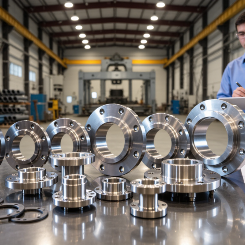
Mechanical flanges support global projects because they allow inspection, replacement, and controlled bolting. They also simplify maintenance around pumps, valves, and pressure vessels. ASME B16.5 covers nominal sizes and pressure classes from 150 to 2500. However, the class number is not a direct pressure value. Never choose by class alone.
Class 150 may suit moderate services, while Class 2500 supports demanding pressure systems. The actual rating depends on flange material, design temperature, corrosion allowance, and gasket selection. For example, carbon steel ratings can fall sharply at elevated temperatures. Engineers should compare process pressure with the pressure-temperature tables, then verify bolts and mating components.
The 2016 NACE IMPACT study estimated global corrosion costs at 2.5 trillion dollars annually, equal to 3.4% of global GDP. Poor flange selection can increase leakage risks and maintenance exposure.
Tips:
Record pressure, temperature, fluid chemistry, and flange material before selecting a class. Check the piping code and require certified material records. In field work, uneven bolt tightening remains a frequent weakness. A calibrated torque tool helps, but it does not replace alignment checks. One detail is often missed: thermal cycling can loosen an apparently correct joint. Recheck the design assumptions. Улар
EN 1092-1 provides a practical language for international flange selection. Its PN 6–PN 400 range covers low-pressure utility lines and demanding process systems. However, PN is not a guaranteed operating pressure. Temperature, material strength, gasket type, and bolt loading also matter.
This point is often missed.
The World Steel Association reported about 1.88 billion tonnes of crude steel production in 2024. That scale reflects the continuing need for reliable, traceable steel components across energy, water, and manufacturing projects. For engineers, EN 1092-1 helps standardize flange dimensions, bolt patterns, and facing options. A PN 16 flange selected in Germany can therefore be checked more easily against a matching component in Brazil or Southeast Asia.
Field experience still exposes weaknesses. Drawings may show only “PN 40,” without naming the steel grade or design temperature. That is not enough. The International Energy Agency’s World Energy Outlook 2024 highlights expanding electricity and infrastructure demand, increasing pressure on equipment reliability. Project teams should verify pressure-temperature tables, corrosion allowances, gasket compatibility, and inspection records before ordering. Small dimensional differences can stop installation. The standard reduces uncertainty, but it cannot replace engineering judgment.
Why Choose Mechanical Flanges for Global Industrial Projects?
ASME B16.47 supports large-diameter connections from roughly DN 650 to DN 1500. These sizes serve pipelines, storage terminals, power facilities, and water infrastructure. The standard addresses flange dimensions, bolt patterns, and pressure classes. This common framework helps teams coordinate across countries and contractors.
A large flange is more than a steel ring. At DN 1200, bolt alignment can affect installation time and gasket performance. Engineers should confirm the selected series, pressure rating, material, facing, and temperature limits. Site teams also need measured pipe dimensions and realistic access for torque tools. Small errors become expensive at this scale.
Mechanical flanges allow controlled assembly and future access. Technicians can inspect, replace, or disconnect equipment without cutting the main pipe. That flexibility matters during shutdowns. It also supports staged construction in remote locations. However, flanges do not solve every problem. Poor bolt tightening can cause leakage. Uneven support can stress the joint.
Some drawings look complete.
In practice, field conditions often disagree. Experienced teams verify face flatness, bolt-hole orientation, gasket storage, and lifting plans before installation. Independent inspection records can strengthen confidence in the connection. One lesson remains easy to miss: larger does not always mean safer. Correct engineering, documented checks, and disciplined assembly determine whether an ASME B16.47 connection performs reliably.
The chart shows the nominal diameter range covered by ASME B16.47, from DN 650 to DN 1500, corresponding to NPS 26 through NPS 60. Mechanical flanges support standardized bolted connections, allowing large-diameter piping systems to be assembled, inspected, maintained, and replaced without field welding at every joint. DN values represent nominal pipe size designations, not measured outside diameters.
Why Choose Mechanical Flanges for Global Industrial Projects?
Material selection often decides whether a flange survives years of pressure, heat, and maintenance. ASTM A105 carbon-steel forgings suit many ambient and elevated-temperature services. They offer dependable strength and broad availability. However, they need careful protection in wet, acidic, or chloride-rich environments.
ASTM A182 covers forged alloy and stainless-steel flanges, fittings, and valves. Grades such as F304 and F316 provide stronger resistance to many corrosive process fluids. Yet “stainless” does not mean corrosion-proof. Chlorides, stagnant water, and poor cleaning can still create pitting. That small pit may grow beneath insulation, where inspection becomes difficult.
The NACE IMPACT study estimated global corrosion costs at about $2.5 trillion annually, equal to roughly 3.4% of global GDP. This figure shows why material decisions deserve engineering attention. On real projects, teams should review design temperature, pressure, fluid chemistry, and weld compatibility together. They should also verify heat treatment, chemical composition, mechanical test results, and positive material identification records. A105 may be economical for a dry steam line, while A182 stainless steel can be more sensible near seawater exposure. The cheaper choice is not always cheaper. I have seen specifications focus on flange rating while overlooking bolts, gaskets, or insulation moisture. That is an avoidable gap. Temperature limits must follow the applicable design code and certified material data, not assumptions.
| Material / Grade | ASTM Specification | Material Family | Minimum Tensile Strength at Room Temperature | Minimum Yield Strength at Room Temperature | Temperature Selection Profile | Corrosion Resistance | Typical Industrial Applications | Key Selection Considerations |
|---|---|---|---|---|---|---|---|---|
| A105 | ASTM A105/A105M | Forged carbon steel | 485 MPa minimum | 250 MPa minimum | Suitable for many ambient and moderately elevated-temperature services. Allowable pressure and temperature must be checked against the applicable design code and flange rating. | Limited resistance in wet, acidic, saline, or oxygen-rich environments. Corrosion allowance, coating, lining, or corrosion control may be required. | General process piping, water systems, hydrocarbons, utilities, and non-corrosive pressure equipment. | Cost-effective and widely available. Not normally the first choice for aggressive aqueous corrosion or chloride-rich service. |
| A182 F304 | ASTM A182/A182M | Austenitic stainless steel, approximately 18% chromium and 8% nickel | 515 MPa minimum | 205 MPa minimum | Retains useful ductility over a broad temperature range. Design limits depend on temperature-dependent allowable stresses, pressure class, and fabrication conditions. | Good general atmospheric and many chemical-service environments. Susceptible to pitting and crevice corrosion in chloride-bearing conditions and to chloride stress-corrosion cracking at elevated temperatures. | Food and beverage systems, clean utilities, chemical processing, general water service, and moderately corrosive piping. | A practical upgrade from carbon steel where cleanliness and general corrosion resistance are important, but chloride exposure should be evaluated carefully. |
| A182 F316/F316L | ASTM A182/A182M | Molybdenum-bearing austenitic stainless steel, approximately 16–18% chromium, 10–14% nickel, and 2–3% molybdenum | 515 MPa minimum | 205 MPa minimum | Suitable for a broad range of cryogenic-to-elevated-temperature services when the design code confirms the required allowable stress and flange rating. | Better resistance to chloride pitting and crevice corrosion than F304. It is not immune to severe chloride attack, marine exposure, or chloride stress-corrosion cracking. | Marine and offshore piping, chemical processing, pharmaceutical systems, salt-containing water, and high-purity services. | Often preferred over F304 when chlorides or higher corrosion resistance are present. The “L” grade supports improved weldability by limiting carbon content. |
| A182 F11 | ASTM A182/A182M | Chromium-molybdenum low-alloy steel | 415 MPa minimum for Class 1; higher strength requirements apply to other classes | 205 MPa minimum for Class 1; higher strength requirements apply to other classes | Designed for elevated-temperature pressure service and improved creep resistance compared with standard carbon steel. Post-weld heat treatment and code requirements may apply. | Better oxidation and high-temperature stability than plain carbon steel, but it is not stainless steel and has limited resistance to aggressive aqueous corrosion. | Boilers, steam systems, power-generation piping, heaters, and high-temperature hydrocarbon service. | Select by class, design temperature, creep requirements, welding procedure, and heat-treatment requirements rather than by nominal grade alone. |
| A182 F22 | ASTM A182/A182M | Higher-chromium chromium-molybdenum low-alloy steel | 415 MPa minimum for Class 1; higher strength requirements apply to other classes | 205 MPa minimum for Class 1; higher strength requirements apply to other classes | Well suited to demanding elevated-temperature service where creep strength, thermal stability, and resistance to oxidation are required. | Improved high-temperature oxidation resistance compared with F11, but it does not provide stainless-steel-level resistance to wet chloride or acidic environments. | High-temperature steam, power plants, refinery equipment, furnace components, and pressure systems with thermal cycling. | Requires careful welding, preheating, post-weld heat treatment, and hardness control in accordance with the governing construction code. |
Mechanical flanges remain practical for global industrial projects because they support inspection, maintenance, and controlled assembly. Their performance depends on more than flange dimensions. Gasket behavior, bolt properties, operating temperature, pressure, and surface condition all influence joint integrity.
EN 1591-1 provides an engineering method for assessing bolted, gasketed flange connections. It checks bolt forces, flange stresses, gasket compression, and expected leakage behavior. A qualified engineer can use these calculations to confirm whether the joint remains tight during operation. The assessment should reflect actual materials, temperatures, tolerances, and assembly conditions. Generic tables may simplify planning, but they can hide important risks.
In field work, a clean flange face and an even tightening sequence make a visible difference. Calibrated tools also improve confidence in the applied bolt load. Torque alone, however, does not prove correct gasket compression. Friction can vary sharply between bolts. That detail is often underestimated.
EN 1591-1 calculations should connect with inspection records, material certificates, and installation procedures. Traceable evidence strengthens technical decisions across different countries and contractors. Experienced teams also review unusual results instead of accepting software output automatically. The method is powerful, but not magic. Input uncertainty remains real.
A small misalignment can change contact pressure. A damaged gasket can defeat an otherwise sound design. Careful review before assembly is usually cheaper than investigating leakage afterward.

Sign up for our mailing list to stay informed and up to date with our latest news and products!
(905) 832 – 0600
2175-A Teston Road
Maple, Ontario
L6A 1T3
(780) 451 – 0238
24790 – 117 Avenue
Acheson, Alberta
T7X 6C2
(604) 882 – 1564
9511 – 194A Street
Surrey, British Columbia
V4N 4G4
(306) 955 – 6005
3926 Arthur Rose Avenue Saskatoon, Saskatchewan
S7P 0C9
(450) 687 – 2721
2750 Rue Bernard-Lefebvre
Laval, Quebec
H7C 0A5